Controller System Menu Overview Micro OCS Series

Horner APG > Blog > Tech Tips > Controller system menu overview Micro OCS Series

The Units have a built-in System Menu, which lets the user view and adjust system settings.

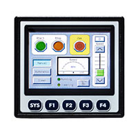
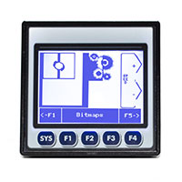
  • For touchscreen units system key can be found by touching top right hand corner of screen and then pressing the sys key
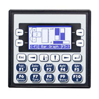
  • For the X2 simaltaneously pressing the up and down arrow will bring up the system menu
  • %sr3 being set to 1 will also bring up the system menu
  • use the ↓ and ↑ (Up Arrow or Down Arrow) keys to select a Main Menu item and press Enter (Return Arrow) to display the item’s Sub-Menu

Set Networks

This sub menu allows setting for the CAN and Ethernet network to be viewed or changed.

CAN Ok? Yes= CAN1 connected to a CAN network and functioning properly

No= Not ready to communicate on CAN network

CAN ID/Network ID 1 to 253 = This node’s CsCAN Network ID; must be unique on network
CAN Baud 125 KB = 125 KBaud CAN network 250 KB = 250 KBaud CAN network 500 KB = 500 KBaud CAN network 1 MB = 1 MBaud CAN network
MAC ID Displays the Ethernet MAC ID of the unit
IP Displays the Ethernet IP address of the unit
NetM Displays the Ethernet net mask of the unit
GatWy Displays the Ethernet gateway of the unit
CAN termination (X2,X4) Yes = 121Ω termination is internally placed between CAN_H and CAN_L terminals

No = No termination present

Network Ok? Yes = connected to a network and functioning properly

No = Not ready to communicate on the network

NOTE: The IP address, Net Mask and Gateway can be changed from the system menu. This is designed for commissioning or temporary field changes. The actual parameters are defined in Cscape under the Ethernet configuration and are reverted to whenever the unit goes from idle to run mode.

View status


Model

XW1yz= Model number of OCS unit

1yz = indicates the installed I/O module

00 = no I/O module


OCS Mode

Idle = OCS is in Idle mode

DoIO = OCS is in Do I/O mode

Run = OCS is in Run mode


Scan Rate(mS)

0.0 = OCS is not in Run mode

0.1 to 999.9= Average number of mS for each ladder scan

OCS Net Use % 0.0 to 100.0 = CAN network bandwidth % used by this OCS node
All Net Use % 0.0 to 100.0 = CAN network bandwidth % used by all nodes
Ladder Size x = Number of bytes in application ladder program
Config Size x = Number of bytes in application I/O configuration
Graphics Size x = Number of bytes in application graphic screens
String Size x = Number of bytes in application string table
Bitmap Size x = Number of bytes in application bitmaps
Text Tbl Size x = Number of bytes in application text tables
Font Tbl Size x = Number of bytes in application font tables
Protocol Size x = Number of bytes in application downloaded protocols
SMS File Size x = Number of bytes in application SMS protocol configuration
Firmware Rev xx.yy = Current firmware version
OS Ver a.b.cd.yz = Current Operating System version
FPGA Rev x.y = Current FPGA version (High Speed IO Sub System)
InitRD Rev x.yz = Bootloader version
Self-Test Ok = All power-on self-tests passed

 Fault = One or more power-on self-tests failed

The View Status Sub-Menu displays up to 19 System Settings. Only the OCS Mode System Setting is editable.

View Diags

  • First 2 system diagnostics are critical if either of them indicate a fault the OCS will not enter or remain in Run mode, problem should be investigated and corrected.


Logic Error: Ok = All executed ladder instructions are legal for loaded firmware

Fault = A ladder instruction not supported by firmware was found

User Program: Ok = Ladder program and I/O configuration loaded successfully

Fault = Ladder program or I/O configuration not loaded or load failed


  • Last 9 system diagnostics are informational, if a warning indicated unit can still enter run mode and remain there but problem should be investigated and corrected
User Graphics Ok = Application graphics objects loaded successfully

Fault = Application graphics objects not loaded or load failed

W-Dog Trips 0 = Watchdog timer has not tripped since the last power-up

x = Number of times watchdog timer has tripped

Net Errors 0 = No CAN network bus-off errors have occurred

x = Number of CAN network bus-off errors that have occurred

Network State Ok = At least one other node was found on the CAN network

Warning = No other nodes were found on the CAN network

Network ID Ok = This node’s CAN Network ID is in the range 1 to 253

Warning = This node’s CAN Network ID was out of range at power-up

Dup Net ID Ok = This node’s Network ID is unique on the CAN network

Warning = This node’s Network ID is duplicated in another node

Clock Error Ok = Time and date have been set

Warning = Time and date need to be set

I/O System Ok = I/O configuration matches the installed I/O and COM modules

Warning = I/O configuration needs updating to match installed modules

Battery Ok = Backup battery operating properly

Warning = Backup battery needs to be replaced


View Protocols

  • View protocols sub-menu is not editable
  • To assign a downloadable protocol to an X4 serial port, select the Protocol Config item in Cscape’s Program menu and then setup a protocol for Port 1 or Port 2 (or both).
  • In the View Protocols Sub-Menu, the currently downloaded protocol, if any, and its version number are displayed for both Port 1 and Port 2.

Set Fkeys

Fkeys: Momentary = %K1-4 bits go On & Off as F1-F10 are pressed & released

Toggle= %K1-10 bits toggle each time F1-F4 are pressed

SYS_Fn enable: Yes = Reset and all clear system functions enabled

No = Reset and all clear system functions disabled


Set Serial Ports

  • For the Dflt Pgm Port System setting, only MJ1-232 can be selected, unless a Modem (XMC) COM module is installed.

Set time\date

NOTE: Not all controllers contain real-time clocks

Controller Time Zone (UTC time): From Cscape 9.70 SP2 and FW 14.22 onwards, UTC time is supported

  • The timezone setting is an hourly offset from UTC time. Set timezone first then local time. UTC time will automatically set based on timezone and local time settings.
  • NTP utilizes UTC time so when using NTP appropriate hourly offset from UTC must be entered into time zone setting.
  • If observing daylight saving set to Yes, otherwise set to No. OCS does not automatically switch to daylight saving however can be done in program. Setting register %SR211 to 1 sets daylight saving. Trigger the move to %SR211 based on a compare function to the RTC date
  • To Set Local Time: The Set Time/Date sub-menu displays three system settings. Time and Date may be edited, and Day is automatically calculated from the Date
  • NOTE: Time and Date are split into three fields each, all of which may be edited. Touch the field or use ¯ or ­ buttons to select a field, then use the ¯ or ­ buttons to edit the field.
Time 16:09:49= Current time (hours:minutes:seconds in 24-hour format)
Date 10-Jun-2013 = Current date (day-month-year)
Day Monday = Current day of week calculated from the Date setting


Set Beeper

Beeper Enable Yes (default) = Enables beeper

No = Disables beeper (does NOT affect ladder access)

Set Screen

Saver enable Yes = Enable screen saver

No (default) = Disable screen saver

Timeout (min) 5 – 1200 = Amount of time in minutes to expire with NO touch activity before activating screen saver (black screen)
Popup Status Off (default) = Disable popup status

Warning = Display popup status only if controller status changes to NOT Ok or NOT Run mode.

On = Display popup status on any controller status change.

Update Time (mS) 2 – 50 = Maximum amount of time to allow for graphics update per scan

Removable Media

If a directory name is highlighted, pressing Enter will switch to that directory showing its files and subdirectories. In a sub-directory, highlighting .. (dot dot) and pressing Enter will move up one directory.

Fail-Safe System

Enable Auto Run

“Enable AutoRun” displays the following options which can be selected:

Enable AutoRun No = OCS will be in IDLE mode after AutoLoad or Automatic Restore.

Yes = OCS will automatically be placed into RUN mode after AutoLoad or Automatic Restore.

Enable AutoLoad No = Does not load AUTOLOAD.PGM automatically when application program is absent or corrupted.

Yes = Loads AUTOLOAD.PGM file automatically from RM when application program is absent or corrupted.


Clone unit

Refer to Clone Unit tech tips page for in depth cover.

Menu Maps